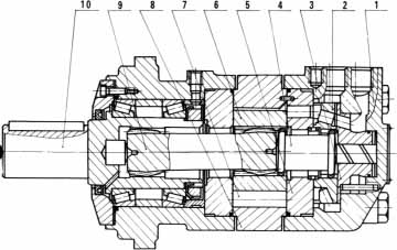
Pressurized oil enters the rear housing (1) through the oil inlet hole through the working cavity between the back plate (5) of the support plate (2) and the rotor (6) and the stator (8). Under the action of oil pressure, the rotor (6) ) Is pressed to the side of the low-pressure cavity and rotates along the internal teeth of the stator (8). The rotation of the rotor (6) includes rotation and revolution, and is transmitted to the output shaft (10) through the long spline shaft (9). At the same time, Through the short spline shaft (4), it is transmitted to the valve plate (2), and the rotor (6) and the valve plate (2) operate synchronously, so that high-pressure oil and low-pressure oil are continuously alternated, and the input pressure and flow rate can be changed to output Different torque and speed. Changing the direction of the inlet of the pressure oil can change the direction of rotation of the hydraulic motor.
|
|
Structure chart
1. Rear shell
2. Distribution plate
3. Support plate
4. Short spline shaft
5. Rear side panel
6. Rotor
7. Needle column
8. Stator
9. Long spline shaft
10 output shaft
|